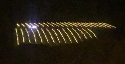
 Compare 2021 to
2023!
I happen to have a CanaKit Raspberry Pi 3 B+ laying around. Here's my attempts at making this work.
BTW: Be sure to buy a "tester". You cannot test the lights easily as they need a very specific control signal to even turn on, so you'll need to have a known-good. I got an Alitove SP105E for $18 (probably from Amazon). It's controlled by a free download smartphone app via bluetooth. (See video below of this things default pattern.)
Note that this page is shown in archeological order, namely newest first. If you want to understand the events in order, start at the bottom.
Most importantly, although I do have the perl/swig version working, I have yet to make time to packagifize and upload to cpan. I will get there eventually.
Here's some videos:
4 panels, xmas trees and PV, daylight.
4 panel test pattern, border and panel IDs, night.
Final, 3 panels, xmas trees and PV, night.
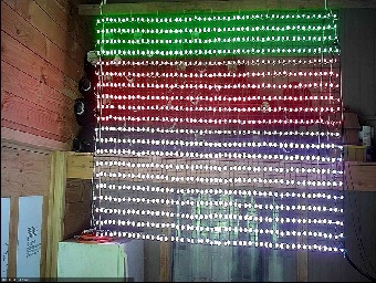 This photo is of my test screen, it's one of the 4 panels described
below, but out-of-season hanging in my workshop. Instead of my normal
20 rows by 50 cols, for testing puproses I have it sectioned to show
multiple channels - the colored sections correspond to DMA channels:
white=ch0 (10 rows), red=ch1 (6 rows), green ch2 (4 rows).
I did find an article that discusses this, but it seemed like I should
be getting no worse than 100ms, as opposed to the near 500ms it seems
to be taking.
Next I realized I'd have to fix the string displayer to double the characters in both height and width in order for them to be readable from the highway. I didn't get to that software work until 2023, I didn't change the character set, I just fixed the displayer routine to be able to take a size multiplier and now use 2. With characters 20x16 they're quite visible at that distance.
This year I decided to expand by a second panel, identical to the first of 50x20, and I'll put them inline so that from a distance it's effectively a 100x20 screen. When I went to buy the strings, they had a discount if you bought 5, so I went ahead and got 6, allowing me to make 3 more panels.
I went ahead and built the 2nd panel, hooked it onto the end of the first, added it to my layout array, and I was off and running (daytime video and night video)! (Note the double size lettering - it is now readable from the highway), although it's only 5 characters wide. (Compare to 20221125 video.) In the daylight video, you can also see the vineyard lights all around.
While I had the 2 panels side-by-side in the shop, I did a quick test by hanging some of the extra strings off the end of this thing, and discovered that a single GPIO PWM pin (I'm using GPIO 18), can only drive 2048 bulbs, so my two panels is all I get... (Ah, but see below!)
When you initialize the neopixel object, you have to give it a GPIO number. I thought I read somewhere that GPIO19 was a second PWM pin, but the initializer says nope. I did some googling and found a reference that 10, 12, 18 and 21 were all usable this way. I whipped up a quick-n-dirty little test app to see if I could get the neopixel object to use other pins. I got it to work with pin 21. I then updated the program enough to see if the program could create neopixel objects for BOTH pins, and control them simultaneously - yes, it works, yay! As mentioned above, I read that there were 4 pins that could be used for this. From my testing on the protoboard, this is not quite true. Although the neopixel lib allows you to initialize with these 4, GPIO10 simply does not do anything; and GPIO12 simply duplicates GPIO18. So this year, I'll leave it with the 4 panels.
So I've expanded the layout array to include an offset to a pin number. I can now go to 2 panels of 50x20 on each of 2 pins, thus giving me an effective screen of 200x20.
Cute video - I've almost completed panel #3, when the cat showed up in the shop to see what I was doing.
Here's an intermediate with 3 panels (daytime). Note the reduced smooth-scroll speed - each panel slows it down dramatically.
Here's the final result in 2023 - 4 panels of 50x20 adjacent and programmed as a single 200x20 screen. Video in daylight with netting visible, and dark (both closeup). And one from near the highway with all 4 panels. Here's a newer one (closeup) with the cute little Christmas tree duplicated to each panel.
 Compare 2021 to
2023!
Note to self: Convert iPhone .MOV files to something the rest of the world can actually use (.mp4):
ffmpeg -y -i IMG_7523.MOV -c:v libx264 -strict -2 -movflags +faststart -loglevel quiet -threads 2 IMG_7523.mp4
Note how the two halves (left vs. right) jump differently - this is the two spearate neopixel.show() calls happening. They are done one immediately after the other, but there's still a notable jump. The .show() call takes a significant amount of time, I'd guess something like 250ms. This is enough to make it jerky. Next year I may have to put the whole thing up and "interlace" with rows going all the way across so the difference will be horizontal instead of vertical. I don't know if this would be an improvement, it's just an idea. Also possible would be to multithread the app - I don't even know if Python is able to do that - sure wish I could do this in Perl!
/etc/resolv.conf.
But a reboot will wipe out your changes. To fix this, you must
edit /etc/resolvconf.conf, and replaceresolve_conf="/etc/resolv.conf"resolve_conf="NO"/etc/network/interfaces.d/interfacesauto eth0iface eth0 inet static address 63.226.250.179 netmask 255.255.255.248 gateway 63.226.250.182 broadcast 63.226.250.182 dns-nameservers 63.226.250.182 207.229.65.53/etc/dhcpcd.conf, adding blocks like:interface wlan0static ip_address=192.168.0.179/24static routers=192.168.0.1static domain_name_servers=207.229.65.53static domain_search=interface eth0static ip_address=63.226.250.179/24static routers=63.226.250.182static domain_name_servers=207.229.65.53static domain_search=raspi-config as su -- nope.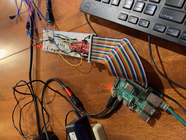 This photo is my test jig, with a 2nd rPi and a protoboard with fanout
board.
Now a quick reminder on how to plug the thing back in when it's been
disassembled...
Raspberry Pi Pinout Guide
Pin 1 is closest to the edge - away from the network connector. On
your protoboard, pin 1 is the end showing the power connections,
namely the brown end wire on the ribbon. Why couldn't they have
used a freakin polarized connector?
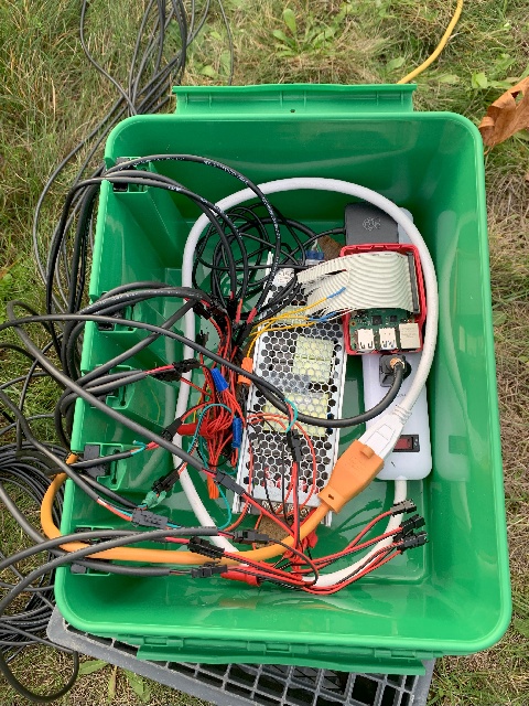 Photo is my production setup - in use, outdoors.
Oh, and BTW - I went to a "large" Sockitbox this year. I now have 20 little connectors for outgoing power, and it was getting rather crowded in there. Shown is with 3 panels wired in, you can see a handful of connectors at the bottom right ready for the 4th panel.
Note also that it is sitting on an upsidedown milk crate. Without
this, the display will work, but the WiFi is not able to bind, meaning
you cannot get in via ssh to make changes. The height of
the milk crate seems to be enough to get to my house WiFi about 300'
up the hill.
Also note that the rPi is in a plastic case (bottom only) so that if
it were to slip around inside the box, it would not get shorted out on
the metal power supply case. Any interference from being so close to
a switching power supply and a 110V power strip has not been a problem
- WiFi does work.
/etc/wpa_supplicant/wpa_supplicant.conf
A problem I put up with all last year, was that I could not get
autostart at boot to work. When I just tried calling it out directly,
I would get a successful startup, but it would suddenly go all wonky
after a few seconds. I assumed this was due to a second process
starting as this script is called at each runlevel, so I added code to
the main python script to exit if duplicate instance. Still no joy.
I tried only invoking on a single runlevel and such, but never got a
startup at all. The last thing I tried was to simply add a 15 second
delay as a diagnostic - that fixed it! I'm guessing that the 2nd
iteration of the program did not properly detect that it was the
second, and the delay is enough to make it work. Here's
my /etc/rc.local/
sleep 15
/home/mikel/ledary/downdown.py
Follows is the code in mainline script to exit on duplicate.
def CheckForDupProcess(process_name):
Count = 0
process_status = [ proc for proc in psutil.process_iter() if proc.name() == process_name ]
if (len(process_status) > 1):
print( "already running - quitting")
exit()
if __name__ == '__main__':
CheckForDupProcess(gProgName)
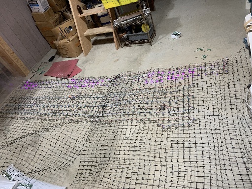 As mentioned earlier, I originally got 10 strings of 50, and
this year got another 10 strings. My original configuration was
a grid of 44w x 11h as I really wanted a little more height than
10 rows. Now that I have additional strings, I've decided to go
to a complete string per row, so will now have 50w x 20h. In
the photo you can see 3 new 50w rows at the top, and a handful
of the old 44w rows yet to be torn out and re-done.
As mentioned earlier, I originally got 10 strings of 50, and
this year got another 10 strings. My original configuration was
a grid of 44w x 11h as I really wanted a little more height than
10 rows. Now that I have additional strings, I've decided to go
to a complete string per row, so will now have 50w x 20h. In
the photo you can see 3 new 50w rows at the top, and a handful
of the old 44w rows yet to be torn out and re-done.The mesh is a piece of plastic deer fencing, 8' high, with roughly 2" squares. Roughly at each junction, a bulb is tied with a vineyard tie (just like the tie on a loaf of bread).
The pink square at the top left is a yoga mat I use to keep from destroying my knees on the cold concrete.
Here's a video of the final result in 2022 - 50w x 20h. I had horizontal smooth scroll working (mostly-sorta) saying "PerennialVintners.com". I also did a vertical line-by-line scroll "Happy holi-days". Oh, and a cute little x-mas tree. The raggedness is greatly improved as this was now tied to a mesh at each bulb., however I tied them where they fell on the line which is not consistent between strings - we'll do better next year. (For 2023 I tied them on actual crosses in the netting which made them fairly consistent.) Note that the white lights in a row across the back are on the top of my vineyard wires, you can see this better in other shots (see 20231116 daylight 2 panel).
Here's a rear view video looking
down the vineyard rows. You can see how it faces the highway,
with cars going by.
I've got my matrix set up in my workshop, and have aimed a webcam at it so I can test it from the comfort of my warm office area as opposed to perched on a stool in a cold shop working on a really old really slow computer!
I've added some new items to the test/idle loop. Some of them
are interesting enough to need explanation, so see external
doc idle loop/test explanations.
I really, really hate Python, but have still been unable to find a neopixel library for perl, so am looking at more recognized solutions. Currently investigating Falcon Player (FPP).
This thing is extensive, and appears to be massively powerful - outright amazing! I'll start a new page here for the FPP version of the project.
apt-get install libxext-dev
cpan install XML:LibXML
cpan install HiPi - nope, still blows chunks
HiPi perl modules
for RPi (hipi.znix.com)
I followed the initial 64 bit
directions, got a bad arcitecture error. Tried 32 bit, this
seemed to complete. Still didn't get hipi installed though.
Tried the cpan install directions, that has gotten it to
install, yay!
apt-get update
apt-get install libmodule-build-perl \

                     libdevice-serialport-perl \

                     libfile-copy-recursive-perl \

                     libfile-slurp-perl \

                     libjson-perl \

                     libtry-tiny-perl \

                     libuniversal-require-perl \

                     libio-epoll-perl \

                     libimage-imlib2-perl \

                     libbit-vector-perl \

                     libxml-libxml-perl \

                     libwww-perl \

                     libperl-dev
cpan -i HiPi
Now when I try running my test program which does not call out
I2C, it simply tries to initialize and do a test neopixel
pattern, I get an error "i2c_write failed with return value -1
at
/usr/local/lib/arm-linux-gnueabihf/perl/5.32.1/HiPi/Interface/Seesaw.pm
line 263."
At least we're getting into the test program
instead of barfing with HiPi not loaded.
The cpan install barfs with a bunch of test failures. Looking
at the output, I think the tests are actually trying to control
the board, and read i/o from it, and interpret the results.
Perhaps my configuration is confusing it? Anyways, I'll just do
a forced install without the tests and see what happens.
find / -name WipringPi -print
cd /root/.cpan/build/
ls -l
Decide which to use, I'm going with the highest numbered.
cd RPi-WiringPi-2.3633-5
make install
My program is now able to run, we're getting past the no such
libary problem. Next is to see if it actually controls the
GPIO... Yes, doing a new WiringPi, and a new Pin, he pin cntrol
works, yay!
Now trying to get adafruit-neopixel operational. Getting
nowhere. Trying HiPi::seesaw...
apt-get install -y libimage-imlib2-perl
cpan install XML::LibXML nope, blows chunks needing XML::LibXML
cpan install Alien::LibXML never mind, this hangs on xmlsoft.org
I built a new system on a new SD card (preloaded with noobs, and
let it do all it's updates), on a new RPi 4B+ (from Raspberry Pi
themselves). I then copied the python program I'd written on
the old RPi that had gotten clobbered (see 20211227 below). Of
course I always backed up the program itself onto an external
server, so even if the SD card had died I wouldn't be screwed!
I tried running the old program, and got No module named
board error.
pip3 install adafruit-circuitpython-nepixel
All is working now, yay!
ws2811_init failed with code -3
      (Hardware revision is not supported)
. I'll work on this
in the future.During the last few days of Dec and first few days of Jan, we had about a foot of snow, and freezing for over a week. This was followed by torrential rainfall, about 6 inches in 24 hours. The sockitbox was not able to handle these conditions. A day or so later, as the rains eased up, the grid stop working, simply no lights. When I opened it up, there was about an inch of water in the bottom of the box. The box was still closed properly so should not have leaked.
I had not seen any significant buildup in previous checks each week or so, so I believe this must be mostly a result of the snow melting as opposed to the heavy rainfall, as we've had significant rain before without this issue. The power supply survived, the wiring is all Ok, the RaspPi did not survive, it's simply dead.
You'll see from the setup photo below, that the Sockit box was simply sitting on a small tabletop, fully exposed to the elements - at one point there was almost a foot of snow on it. A side note, I did observe that there was the same amount of snow on it as on the balcony railing, which means it was not generating significant warmth - this means my power supply is reasonably sized, I'm not holding in excess heat.
Next year I will do something to protect the sockit box, perhaps simply stuff it in a plastic garbage bag, or maybe set it under the table, or place a piece of plywood on top. Here's a video of the final test pattern. It starts with the full alpha/numeric test with scroll, then "Perennial Vintners", and a candy cane red/white stripe. Same as previous plus video some test patterns in other vids below, including horizontal blank and snowstorm. Here's a video of the Alitove SP105E pattern - video made on a cold, rainy, windy night on my cellphone - please forgive.
Oh, and if I was to do it again, I'd go with the 12V instead of the 5V - perhaps there would be less trouble with the dimming strings further down the line that way.
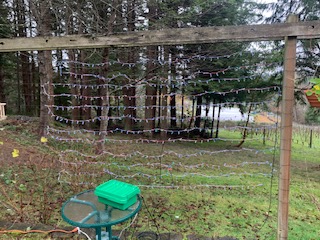 I've finally gotten things mostly
working, although I'm very disappointed with the ability to put text
on the "screen".
I've finally gotten things mostly
working, although I'm very disappointed with the ability to put text
on the "screen".I've simply strung the light strings along a set of horizontal wires to build a grid. Be sure that each row has the same number of bulbs. You will "lose" a few bulbs in the gap between rows (assuming like mine they are a more than one bulb distance apart).
The difficult part is that the length of wire between "bulbs" is very
inconsistent, so you cannot get a clean grid this way - which makes
lettering too ragged to read. The fix will be strictly mechanical,
but right now I've been concentrating on the other facets of the
project.
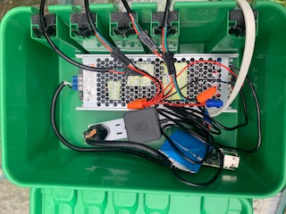 I used a "sockitbox", size
"medium" to hold the guts. It's a normal old Raspberry Pi. I
originally built it with a CanaKit 3B+, but in the process I managed
to kill the UART signal output, so had to replace it, this time with a
4 from Raspberry Pi themselves.
What they don't tell you, is that although these LED strings can connect together in a long line, they won't be able to run that way. I don't know why this happens, the wire between the bulbs appears to be of sufficient gauge to have a long string, but evidently it's not, as the bulbs will be noticably dimmer into the 3rd string, and outright dead by string 4 or so.
My original setup was a plastic power block with Alitove branding (like you have for a laptop) rated at 5V 75W. This was not sufficient. I got two more, which filled up the Sockitbox, and wired them in at each 3 strings - still not sufficient. Bottom line is that each string, at full bright and white, seems to take about 50W. I dumped the block supplies into a box in the garage with a sigh while lamenting $100 wasted, and ordered a MeanWell UHP-500-5 power supply which seems to be perfect (in photo). The 3 blocks together could manage 225W, this one is rated at 400W, takes less space, and costs about the same.
Note that buried under the blue tape is simply a 40 pin connector, plugged into the RPi board, with a ground wire and GPIO 18 (physical pin 12), passed through to the 3 pin connector for the LED string.
One thing I have noticed is that one of my test patterns, which
was cribbed from a neopixel demo, is supposed to have a rainbow
background. This DOES work when I have a single string on my
dining room table, but is a solid green background when outdoors
on the "screen". I did not spend additional effort on this yet,
so not sure what needs to be done here. I'm guessing adding a
transistor to drive the signal line instead of relying on the
meek rPi output directly might be the fix.
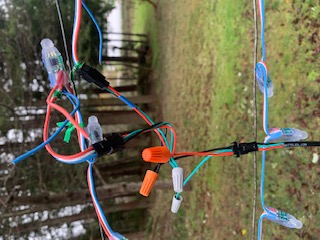 At each 3 strings, I've had to add a junction in for power, and run in
an additional power wire. I bought a box of the same connectors that
the strings use, and made custom "Y" connectors that pass the signal
wire through and bring in power, then run a wire back to the box. The
wire I'm using is 18/3 "max bright led cable", but any decently
jacketed for weatherproof 18/3 will do.
In photo, male towards right goes into the end of a string, the female to the left goes to the next string, and the extra jack on the bottom is one of the additional power lines from the box. Note that the green (signal) wire is connected through the string connectors, but is capped off going back to the box. I had already made this power wire as an "extension cord" for the whole string, but that layout wasn't effective.
If I were to start over, I'd simply put a 2-pin version of the same kind of connector onto the extra little wires sticking out at the start of the string, I'm sure that's what they're there for. I'd do this for half the strings, and bring a power wire out to every 2nd string.
Click here for early attempt video. It starts with a "border" test, but I hadn't yet gotten it to blank the "unused" bulbs between strings. You can see how ragged the right edge is due to the inconsistent bulb spacing. The rest of the pattern is simply tests I wrote trying to get to scrolling and such.
Here's a later attempt including lettering.
It starts with full on white so as to test the power supply and
wiring, you can see I really need to bring in more external power
wires as the last row is definitely fainter and yellowish. Currently
we have power taps at 2, 4, 6, 8. Follows my business name
"Perennial" Vintners, where you can see the ragged look from the
ill-spacing. (I had to create the entire character set by hand.)
Follows is a snowfall that almost looks nice, and some more
learning/test patterns.
As documented below, I gave up on FreeBSD and Perl, and now use
Raspbian ("noobs") which came pre-loaded (it's just Linux, so I'm good
here), and Python which is a terrible, terrible farce of a language,
but - it has NeoPixel suport.
In a nutshell, I build an array by hand of the rows by bulb number so that I can simply loop through them as an array, and not have to worry about the unused bulbs between rows. e.g. first row we use bulb 0 through bulb 39, then there's a 2 bulb gap, then the next row is bulb 42 through 81, etc. Also this array tells us if we're going left-to-right or vice versa with a 1 or -1. This little array is at runtime turned into a single linear array so we can simply index through.
OutputArray = [
You'll use the neopixel module:
[ 0, 39, 1], # 2
[ 42, 81, -1], # 2
[ 84, 123, 1], # 2
[126, 165, -1], # 2
[168, 207, 1], # 1
[209, 248, -1], # 2
[251, 290, 1], # 2
[293, 332, -1], # 2
[335, 374, 1], # 2
[377, 416, -1], # 2
[419, 458, 1], # 2
[460, 499, -1] # 2
]
def buildtranslateary():
idx = 0
for i in range(len(OutputArray)):
if OutputArray[i][2] > 0:
for j in range(OutputArray[i][0], (OutputArray[i][1] + 1), OutputArray[i][2]):
TranslateIndexAry.insert(idx, j)
idx = idx + 1
else:
for j in range(OutputArray[i][1], (OutputArray[i][0] - 1), OutputArray[i][2]):
TranslateIndexAry.insert(idx, j)
idx = idx + 1
def just_fill(r, g, b):
rowlen = ((OutputArray[0][1] - OutputArray[0][0]) + 1)
collen = len(OutputArray)
for j in range(collen):
for i in range(rowlen):
dark = (j * rowlen) + i
darkoffset = (TranslateIndexAry[dark])
pixels[darkoffset] = (r, g, b)
pixels.show()
pixels = neopixel.NeoPixel(pixel_pin, num_pixels, brightness=base_bright, auto_write=False, pixel_order=ORDER)
To autostart your program when the RPi boots (so you can run
"headless"), be sure to get the program so that it will run simply by
invoking it on the command line. You may to have to dork with the
"shebang" syntax (the first line in the file with the "#!") in order
to get it to kick off the correct python. Then add it
to /etc/rc.local, which btw is run as root,
which is necessary for this to work. (Python errors with "cannot
create mailbox" or some other such useless msg if you try to do the
neopixel module without root.)
From here, you're on your own, hope this helped you get going with
your project!
board.py file, I noticed reference
to os.environ('BLINKA_FORCEBOARD'). I poked around in
the constants/boards.py and found "RASPBERRY_PI_3B_PLUS",
which should be this CanaKit, so I tried:setenv BLINKA_FORCEBOARD RASPBERRY_PI_3B_PLUSdetect.py script (below), but I
still get errors from test_leds.pypip install
rpi-gpio I get a mass of c compilation errors. Giving up for
today.
Attempting to get python and NeoLights working.
Installed python, got 3.7
Following:
https://learn.adafruit.com/circuitpython-on-raspberrypi-linux/installing-circuitpython-on-raspberry-pi
I don't have 'apt-get', so am skipping that.
I have 'pip', not 'pip3'.
I'm operating as 'root' thus no 'sudo'.
sudo pip3 install --upgrade setuptools
sudo pip3 install --upgrade adafruit-python-shell
pkg install wget
rehash
wget https://raw.githubusercontent.com/adafruit/Raspberry-Pi-Installer-Scripts/master/raspi-blinka.py
python raspi-blinka.py
Says "none detected".
Blinka Exiting due to error: Non-Raspberry Pi board detected. This must be run on a Raspberry Pi
Other website had me do:
pip install rpi_ws281x
This happened Ok some hours ago, but now it's barfing on missing
'c' include files. Looking around, this seems to be a known
problem with MacOS. Looks like some decls have been moved
around and thus should no longer be looked for in the old
no-longer-existing files. I will create empty files as they're
called out in hopes this will fix it.
cd /usr/include
touch sys/sysmacros.h
mkdir linux
touch linux/ioctl.h
touch byteswap.h
touch linux/types.h
I give up - now it's asking
for linux/spi/spidev.h which I'm sure
won't be in other files. Deleted all the above.
More attempts I've stumbled through:
https://learn.adafruit.com/neopixels-on-raspberry-pi/python-usage
This one helped me get it wired. I know the string works as
when I bought the string, I also got a little $18 controller
that talks to your phone via bluetooth, specifically in order to
be able to test it. I have not seen it light in this config,
however the first problem is the above software issues.
https://www.youtube.com/watch?v=KJupt2LIjp4